This project was built for Miner Street Recordings, a recording studio in the Fishtown neighborhood of Philadelphia. This is the studio where Weathervane Music’s Shaking Through video series is filmed.
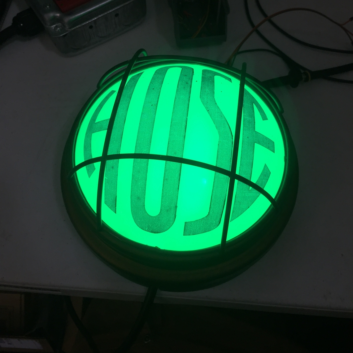
The finished product can best be described as a “Recording When Lit” sign that is controlled wirelessly by either the Pro Tools DAW or a manual button press.
At the request of Brian, the studio’s owner, I built the indicator light into an old novelty light fixture which had been kicking around the studio for a while.
I started the project by defining the functionality of the device.
I wanted a simple user interface and with this goal in mind the finished product has only one toggle switch and one button that also lights up to serve as an indicator of the recording light’s current state.
The toggle switch chooses whether the light will be controlled manually with the button or automatically by listening for Midi messages from Pro Tools.
The Light Hardware
In many ways despite being the most physically complex part, designing the light fixture itself was the easiest part of the project. Since I already had the translucent dome and metal structure to work from I designed the base around its dimensions.
Light Mechanical Design

All of the CAD work for this project was performed in Autodesk’s Fusion 360.
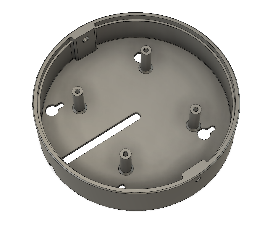
This is the main structure of the fixture, all of the electronics fit inside and the dome cover fastens over it using two M5 screws.
 A flat panel sits into the base and rests on the raised lip and securing pillars.
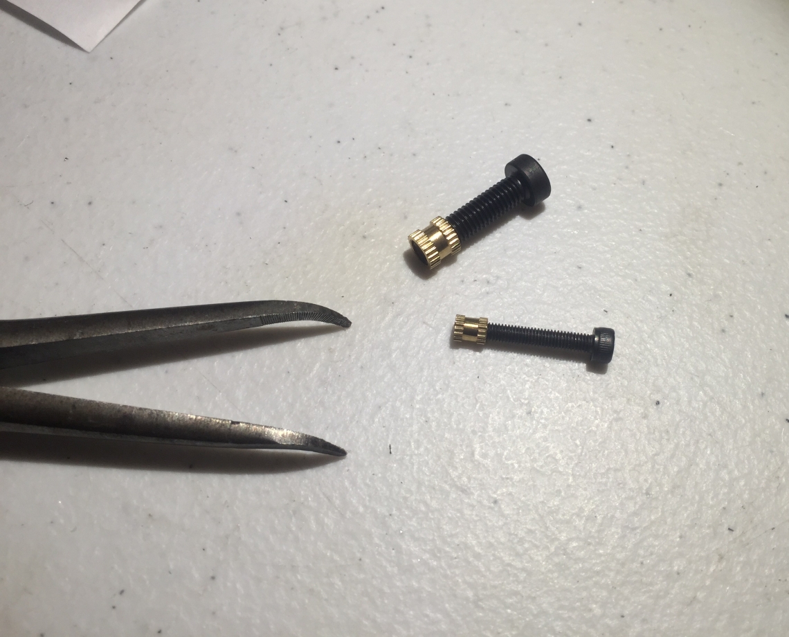 I am a big fan of using heat set inserts in 3d printed parts, these parts are super cheap and lend a professional look to the final product. Here I used two M5 inserts on the sides and four M3 inserts pressed into the pillars to hold the top panel in place.
Light Electronics
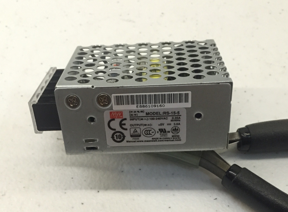 For electronics I used a 5v 3A Mean Well power supply to handle the 120v to 5v conversion. I chose this supply as it is a proven design from a well known manufacture.
I may not always be around to fix things that go wrong with the light so it was important to me to use quality parts that could be sourced again in the future if they ever need replacement.
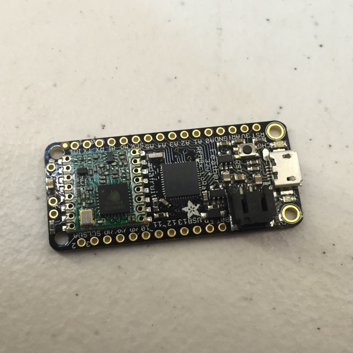
In this vein I used an off the shelf microcontroller development board in both the light and its controller. This is the Adafruit Feather lora 32U4 it is an Arduino compatible development board with a built on lora radio module operating in the license free 900MHz ISM band. This board is a good fit for the project as it has the built in lora radio as well as Arduino USB MIDI library support.
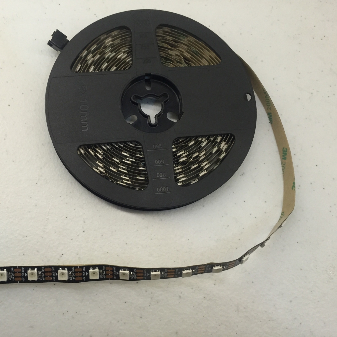
Rather than building this light using traditional RGB led strips I used WS2812 individually addressable RGB led strip commonly referred to as Neopixels.
By using these I did not need to worry about making a traditional RGB led controller and I could program cool light effects such as the rainbow party mode that made its way into the final product.
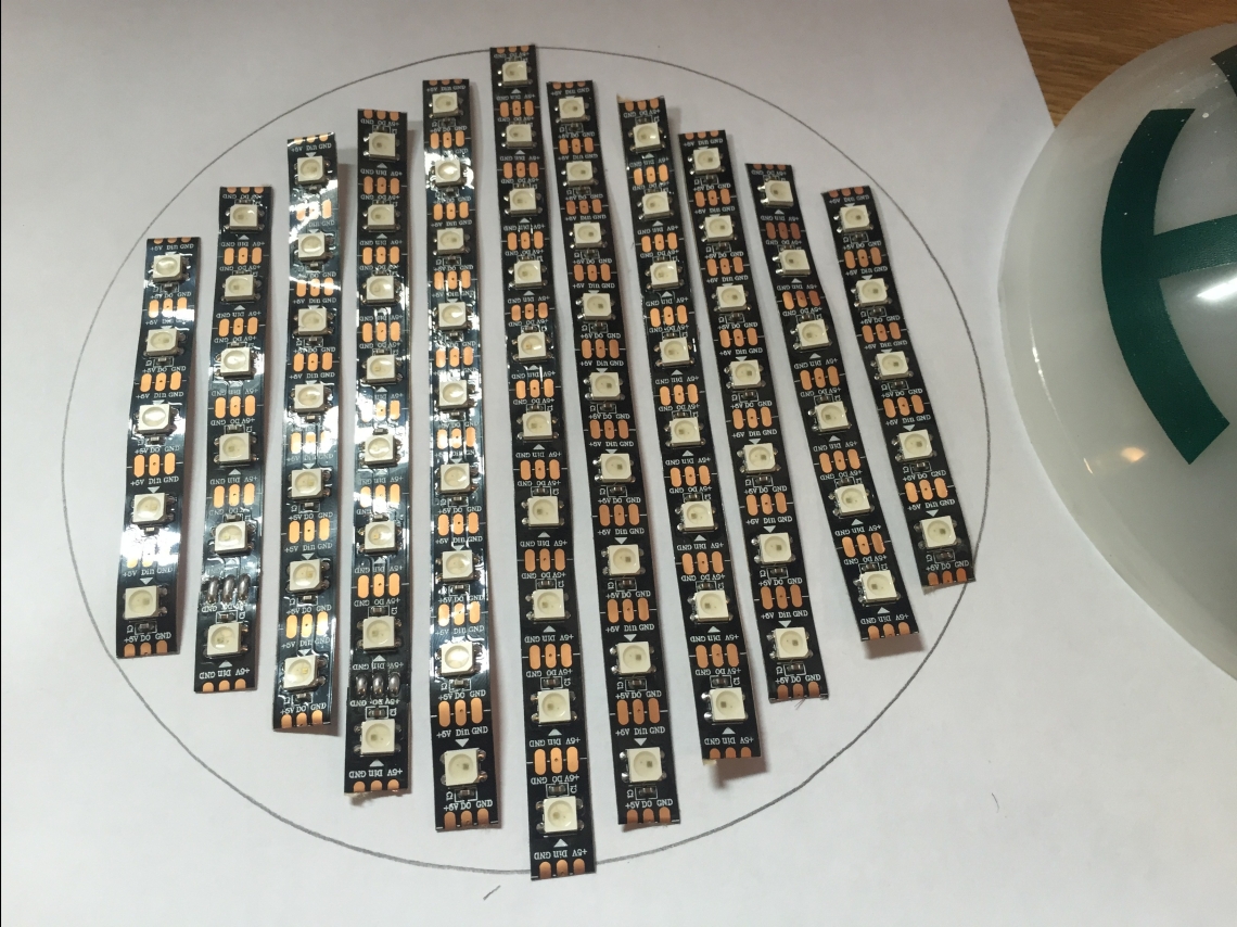
I laid out the LED strip such that strips of it would fit onto the removable top panel of the fixture.

I then glued the strips down to the panel and wired them together.
I found that the 3.3v logic level of the Feather dev board was not enough for the WS2812 strip that I used. The strip should be able to work from this logic voltage but a simple logic level converter solved the problem nicely.

After strain reliving the temporary power cord the light fixture was ready and it was on to the controller.
The Controller Hardware
I decided to build the controller into a 19 inch rack enclosure.
Since real rack enclosures are remarkably expensive and I did not need too much space I made my own enclosure by modifying a 1U rack blank.

I engraved the lettering using my Shaper Origin handheld CNC router.
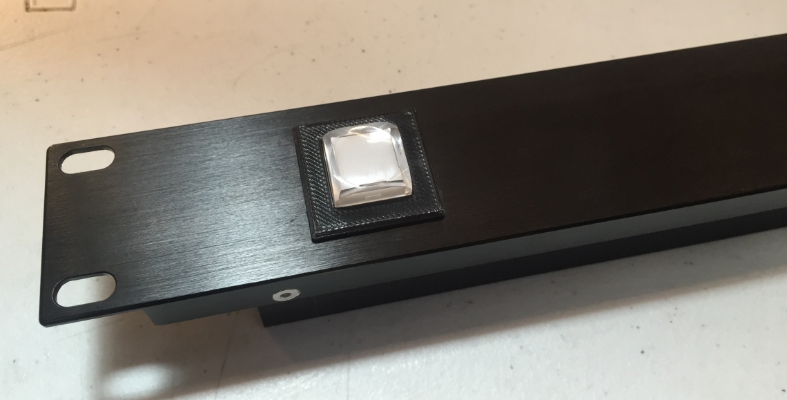
For the illuminated button I cut a square hole by first drilling out the corners then I used a coping saw to cut the rough shape before switching to a file to clean up the edges. I designed and 3d printed a cradle to accept the NKK illuminated switch which snap fit into place.

I mounted the electronics to the back of the rack blank and designed a 3d printed rear cover that also holds the USB jack for power and Pro Tools control. Throughout the assembly of this piece I covered it in blue painter’s tape to protect the nice anodized surface from scratches.

The rear cover is split into two halves so that it would fit onto the bed of my printer. A thin connector holds the halves together. The rear cover panel assembly is held in place with 8 flat head M3 screws that are counter sunk flush with the sides of the rack blank.

The Controller Electronics
Similar to the light fixture I used an Adafruit Feather lora 32U4 dev board for the controller. This allowed for lora wireless as well as USB MIDI control all in one conveniently compact package. I used the 32U4 version of this dev board but the M0 version would likely work just as well and would have more available RAM.
With the exception of two current limiting resistors for the LED indicator under the NKK switch I used no external electronics on the controller’s circuit board.
Firmware
The firmware for the light side of this project was reasonably easy to implement.
Initially I had a tough time getting the lora radio working correctly but once I got that figured out the firmware coding process went smoothly.
For the controller side I had a bit of a learning curve when it came to the MIDI implementation. Eventually I got the firmware to the point that the controller would talk to Pro Tools and emulate a Mackie HUI. I never managed to get the heartbeat function of the original HUI implemented properly. Luckily in modern versions of Pro Tools (I tested the project with Protools 11) you can choose to ignore the lack of heartbeat from the controller and it works just fine.
Throughout this firmware development process I relied heavily on the reverse engineered Mackie HUI MIDI spec.
Pro Tools Setup
To get the controller working with Pro Tools no special drivers are necessary.
Simply plug the controller into the computer, open Pro Tools and set up the MIDI device like you would any other MIDI controller.
The controller enumerated on my computers as a “Feather” and all I had to do was tell Pro Tools that this controller was in fact a Mackie HUI.
This project will likely not work with DAWs other than Pro Tools without some easy modification of the code.
I was able to figure out when Pro Tools was recording and playing back based on the control state of the led indicators on the original HUI hardware. It is likely that other DAWs such as Logic, or Reaper would light these leds in different patterns than Pro Tools does. Pro Tools lights the record led whenever a track is armed and lights the play led when a track is playing. Only when both of these leds are lit is the the software recording.
Building Your Own
While I have made my firmware open source and available for use, please note that it is not the cleanest code in the world and may at times be buggy. No warranty is expressed or implied so use it at your own risk.
If you are looking for an easier but more expensive commercial solution for doing most of what this project accomplishes one exists here. I have not used it but it seems to have good reviews.